About bipinnishad

Hey ! I am Bipin Kumar Nishad the guy behind the blog. I was born on 2nd November,1993 in Allahabad a wonderful place where I became a dreamer. Where the colors & the rhythm of the air makes me creative and sensitive.I’m following a bachelor’s program in B.Tech in the stream of Electrical Engineering from ITM University,Gwalior ,batch 2011-2015. Well enough about that since more about my professional background can be found here. In this blog I will share with you everything that inspires my Delirium World. The one that makes me feel happy creative active where I dream and move with the rhythm of my life. I am sincere and hardworking and like to do things in a perfect manner. My goal in life is to solve the problems of the world using best of my knowledge and skills. I also like to know the secrets of the world and its history. My aim with this blog is to share my knowledge to as many people as I can to realize their own dreams and building their future.What you can find on the blog is little bits and pieces of my daily life, things I enjoy, places I’ve been, thought on current trends, and everything in between.

Triac

Introduction to TRIAC

Triacs are widely used in AC power control applications. They are able to switch high voltages and high levels of current, and over both parts of an AC waveform. This makes triac circuits ideal for use in a variety of applications where power switching is needed. One particular use of triac circuits is in light dimmers for domestic lighting, and they are also used in many other power control situations including motor control.

images (1)

The triac is a development of the thyristor. While the thyristor can only control current over one half of the cycle, the triac controls it over two halves of an AC waveform. As such the triac can be considered as a anti-parallel connection of thyristors with the two gates connected together and the anode of one device connected to the cathode of the other, etc.

Triac symbol for use in circuit diagrams

triac


How does a triac work?

Before looking at how a triac works, it helps to have an understanding of how a thyristor works. In this way the basic concepts can be grasped for the simpler device and then applied to a triac which is more complicated.

For the operation of the triac, it can be imagined from the circuit symbol that the triac consists of two thyristors in  anti-parallel to each other. The operation of the triac can be looked on in this fashion, although the actual operation at the semiconductor level is rather more complicated.

triac..

When the voltage on the MT1 is positive with regard to MT2 and a positive gate voltage is applied, one of the thyristors conducts. When the voltage is reversed and a negative voltage is applied to the gate, the other thyristor conducts. This is provided that there is sufficient voltage across the device to enable a minimum holding current to flow.

Comparison of SCR and TRIAC waveforms:

triac1


Advantages of TRIAC

1. Triac turns OFF when the voltage is reduced to zero.

2. Single gate controls conduction in both directions.

3. Triac with high voltage current ratings are available.

4. Triac is a bidirectional device, it conducts in both direction.

Disadvantages of TRIAC

1. Gate has no control over conduction once Triac is turned ON as in the case of an SCR.

2. Triac has very high switching delay.

3. Triac is not suitable for DC power applications.

Application

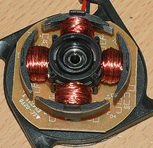
Low power TRIACs are used in many applications such as light dimmers, speed controls for electric fans  and other electric motors, and in the modern computerized control circuits of many household small and major appliances .


Brushless DC Motor

1384845326_527388890_1-Brushless-Dc-motor-1200-rpm-780-gm-thrust-30A-ESC-Morar (1)


Brushless DC electric motor (BLDC motorsBL motors) also known as electronically commutated motors (ECMs, EC motors) are synchronous motors  that are powered by a DC electric source.

The rotor part of a brushless motor is often a permanent magnet synchronous motor  but can also be a  induction motor .

kk

Brushless motors may be described as stepper motor, however, the term stepper motor tends to be used for motors that are designed specifically to be operated in a mode where they are frequently stopped with the rotor in a defined angular position.

Brushless motors  have the armature winding having which is stationary and the permanent magnet at the inside the  yoke part of motor which rotates along with shaft but the armature winding is stationary.

Brushed DC motors develop a maximum torque  when stationary, linearly decreasing as velocity increases. Some limitations of brushed motors can be overcome by brushless motors; they include higher efficiency and a lower susceptibility to mechanical wear. These benefits come at the cost of potentially less rugged, more complex, and more expensive control electronics.

220px-Poles

A typical brushless motor has permanent magnets which rotate and a fixed armature , eliminating problems associated with connecting current to the moving armature.

Brushless motors offer several advantages over brushed DC motors, including more torque per weight, more torque per watt (increased efficiency), increased reliability, reduced noise, longer lifetime (no brush and commutator erosion), elimination of ionizing sparks from the commutator, and overall reduction of electromagnetic interference (EMI). With no windings on the rotor, they are not subjected to centrifugal forces, and because the windings are supported by the housing, they can be cooled by conduction, requiring no airflow inside the motor for cooling. This in turn means that the motor’s internals can be entirely enclosed and protected from dirt or other foreign matter.

Brushless motor commutation can be implemented in software using a microcontroller or microprocessor computer, or may alternatively be implemented in analogue hardware.

maxon-70-Watt-Brushless-DC-Motor

The maximum power that can be applied to a brushless motor is limited almost exclusively by heat;too much heat weakens the magnet and may damage the winding’s insulation.

When converting electricity into mechanical power, brushless motors are more efficient than brushed motors. This improvement is largely due to the brushless motor’s velocity being determined by the frequency at which the electricity is switched, not the voltage.

brushless-dc-motors-000067452-4

APPLICATION

Heating and ventilations- HVAC and refrigeration.

Industrial Engineering:-

                      Motion control systems

                      Positioning and actuation systems

Model Engineering:-

In air craft ,Helicopter,Quard copter.

Radio Controlled Cars.

Working of SCR

SCR (Silicon Controlled Rectifier) :-

  • SCR  is three terminal device Anode ,Cathode ,Gate .

07fae21672fc094f9c5a3294c309797bc283fb09_large

  • Anode and Cathode are connected in series with the power circuit and the Gate signal is applied from the cathode.
  • The silicon control rectifier is the oldest and most popular thyristor. It is an extremely reliable device and can be expected to deliver billions of operations .
  •  The SCR (Silicon Controlled Rectifier) is built in one PNP and one NPN transistor.The basic structure of SCR is below.

SCR-Schematic-Symbol

  • N1 layer is the thickest of all layer and it is very less doped.
  • N2 layer is very thinest of all layer an highly doped.
  • P1 & P2  layer are nearly same , thicker than N2 and less highly doped than N2 .
  • Due to above , the Junction  J3 has very low breakdown voltage in either direction.
  • So, J3 cannot support high voltage.

Working :-

  • If SCR  is in Forward Blocking mode then i.e. input to  anode is +ve and cathode is -ve then SCR  works consists of three diode – D1- (P1 N1) , D2 – (N1 P2) ,D3 – (P2 N2).
  • D1 will be Forward Biased, D2 will be Reverse Biased , D3 will be Forward Biased     So,depletion layer at Junction J2 will increased and which will block the SCR.
  • To trigger the SCR we need to decrease the depletion layer of J2 .This is done by applying the gate signal which will decrease the depletion layer of J2  and  trigger the SCR. That’s why gate terminal is kept near junction J2.

This is the normal mode of operation for of  thyristors.

  •              An external gate pulse or signal is used to switch ON  the SCR.
  • Gate signal used  only for starting of  SCR but does not have control to make SCR OFF.
  • That’s the reason for the use of the Gate terminal .

There are many more ways by which SCR can turn ON which are as follows:-

  1. By avalanche: When the anode is made much more positive then the cathode, Forward break over occurs and latch the device on.
  2. By rate of change: If the forward bias voltage across the device increases very quickly, a current will flow to charge the collector-base capacitance of the PNP transistor. This charging current represent base for the NPN transistor and turns it on
  3. By high temperature: Reversed-biased silicon junction show a leakage current that approximately doubles for every 8° C temperature rise.At some temperature, the leakage current will reach a level that latches the SCR ON.
  4. By light Energy: Light entering the junction area will release electron-hole pairs and letch the SCR on.

The Transistor structure of a SCR :- 


 dd

The equivalent two transistor structure is below:-

 ss

SCR volt-ampere characteristics curve:-

sdd


  •  Suppose Ig=0 and SCR  is F.B. therefore J1 &J3 are in F.B. and  J2 is in R.B. so,the entire voltage will is blocked by  J2 .
  • If applied voltage is greater then junction voltage of J2 (VBO) then device goes into conduction mode .
  • From 0 to VBO  the current flowing is very small only leakage current  and once device is in conduction mode then the current is limited by the  load .
  • Ig=0 so the voltage applied should be higher than VBO   .

sxassx


  • By suppling +ve gate current device goes into conduction mode and the voltage  at which device goes into conduction mode also reduces.
  • But the Gate signal should be present till the through the device is higher than the latching current.
  • When device goes into conduction mode then gate current should be removed because it do not control the device at this time.

This is all about some basic working of the SCR .


What are Lightning Arresters ?

 lightning arrester

Lightning can strike the overhead power line which enters our house, or a main power line that is blocks away from our home.Lightning can strike an object near our home such as a tree or the ground itself and cause a surge.

Voltage surges can be created by cloud to cloud lightning near our home. A highly charged cloud which passes over our home can also induce a voltage surge.Voltage surges can also be caused by standard on and off switching activities of large electric motors or pieces of equipment.

When a voltage surge is created, it wants to equalize itself and it wants to do it as quickly as possible. These things seem to have very little patience. The surges will do whatever it takes to equalize or neutralize themselves, even  it can short circuiting all of our electronic equipment.

The method of providing maximum protection for equipment is done by providing grounding. Which is efficiently done by using Lightning Arrester(or Surge Diverts).

Untitled

Lightning arrester is device which provides an easy conducting path or low impedance path for the flow of current when system voltage increases more than the design value and regains its original properties of an insulator at normal voltage.

Working Principle of Lightning Arrester:-

The earthing screen and ground wires can well protect the electrical system against direct lightning strokes but they fail to provide protection against traveling waves, which may reach the terminal apparatus. The lightning arresters or surge diverts provide protection against such surges. A lightning arrester or a surge diverted is a protective device, which conducts the high voltage surges on the power system to the ground.

lightning-arrestor

It consists of a spark gap in series with a non-linear resistor. One end of the diverter is connected to the terminal of the equipment to be protected and the other end is effectively grounded. The length of the gap is so set that normal voltage is not enough to cause an arc but a dangerously high voltage will break down the air insulation and form an arc. The property of the non-linear resistance is that its resistance increases as the voltage increases and vice-versa.

Lightning_Arrestors

Types of Lightning Arresters:-

  There are several types of lightning arresters in general use. They differ only in constructional details but operate on the same principle, providing low resistance path for the surges to the ground.

  • Rod arrester.
  • Horn gap arrester.
  • Multi gap arrester.
  • Expulsion type lightning arrester.
  • Valve type lightning arrester.
  • Silicon Carbide Arrestor.
  • Metal Oxide Arrestor.

This  is all about the basics of  Lightning Arrester.

What is Stepper Motor ?

STEPPER MOTOR    

      Stepper_Motors

Industrial Motors are used to convert electrical energy to mechanical energy. They are neither precision speed nor precision positioning devices.For an automated systems, precise speed and precise positioning are required.To fulfill these limitations stepper motors are used.

Stepper motor rotates through a fixed angular step in response to each input current pulse received by its controller. So it is named as stepper motor. 

step_motor_cutaway

The Stepper Motor becomes very popular because it can be controlled directly by computers, microprocessors and programmable controllers.

The only moving part in a stepper motor is its rotor. The rotor has no windings, commutator or brushes. Because of these feature the motor is quite robust and reliable.

DSC00108-300x225

Step angle:
The angle through which the motor shaft rotates for each command pulse is called the step angle.

The relationship between steps per revolution and step angle is given by the following formula:-
                      Step angle = 360° / [No. of steps per revolution]
Smaller the step angle, greater the number of steps per revolution and higher the resolution or accuracy of positioning obtained.

Some stepper motor operates upto 20,000 steps per second. Still it remain fully in synchronism  with the command pulses.

How-stepper-motor-works7

When the pulse rate is high, the shaft rotation looks like continuous. Such an operation of stepper motor at high-speed is called slewing’.

Types:
1. Variable Reluctance Stepper Motor.
2. Permanent Magnet Stepper Motor.
3. Hybrid Stepper Motor.

motor-pas-cu-pas-stepper-300x136

Applications-

1.Stepper Motors are used in a variety of automation applications in which a relatively small amount of torque is needed.

2.Typical applications include rotary table control, wire-harness assembly, laser or pen positioning, and office peripheral equipment control.

3.Stepper motors can be used for precise positioning, without the need for a complicated position indicating feedback system.

Operation and Principle of Buchholz Relay in transformer

                                      buchholz-relay

Buchholz Relay in transformer is an oil container housed the connecting pipe from main tank to conservator tank. It has mainly two elements. The upper element consists of a float. The float is attached to it in such a way that it can move up and down depending upon the oil level in the Buchholz Relay Container. One mercury switch is fixed on the float. The alignment of mercury switch hence depends upon the position of the float.

Working Principle-

                     transf_Buchholz_en

  1. Whenever there will be a minor internal fault in the transformer such as an insulation faults between turns, break down of core of transformer, core heating, the transformer insulating oilwill be decomposed in different hydrocarbon gases, CO2 and CO. The gases produced due to decomposition of transformer insulating oil will accumulate in the upper part the Buchholz Container which causes fall of oil level in it.2
  2. Fall of oil level means lowering the position of float which cause  tilting of  the mercury switch. The contacts of this mercury switch are closed and an alarm circuit energized. Sometime due to oil leakage on the main tank air bubbles may be accumulated in the upper part the Buchholz Container which may also cause fall of oil level in it and alarm circuit will be energized. By collecting the accumulated gases from the release pockets which is on the top of the relay and by analyzing them one can predict the type of fault in the transformer.                                                                                          
  3. More severe types of faults, such as short circuit between phases or to earth and faults in the tap changing equipment, are accompanied by a surge of oil which strikes the baffle plate and causes the mercury switch of the lower element to close. This switch energized the trip circuit of the Circuit Breakers associated with the transformer and immediately isolate the faulty transformer from the rest of the electrical power system by  tripping the Circuit Breakers associated with both LV and HV sides of the transformer.                                             buchholz_relay
  4. The Buchholz Relay few times starts working without any fault in the transformer. For example, when oil is added to a transformer  air may get in together with oil, accumulated under the relay and thus cause a false Buchholz Relay operation.
  5. That is why mechanical lock is provided in that relay so that one can lock the movement of mercury switches when oil is topping up in the transformer. This mechanical locking also helps to prevent unnecessary movement of mercury switches during transportation of the Buchholz Relays.

What is Main Difference b/w Electrical and Electronics Engineering?

What is Main Difference b/w Electrical and Electronics Engineering?

the-structure-of-power-system-horz

According To Wikipedia;

Electrical engineering is a field of engineering that generally deals with the study and application of electricity, electronics, and electromagnetism.

Electronics engineering, is an engineering discipline where non-linear and active electrical components such as electron tubes, and semiconductor devices, especially transistors, diodes and integrated circuits, are utilized to design electronic circuits, devices and systems.

but this is the main difference between electrical and electronics engineering is:-

Electrical Engineering = Study and Utilization/Application of Flow of Electrons.

Electronics Engineering = Study and utilization/Application of Flow of Charge ( Electron & Holes).

As we know that we study only the flow of Electrons in a Conductor and insulator,
but in case of Semiconductor, we study both of flow of electrons ( Negatively Charge) and hols ( Positively Charge).

Also Note that ” Electronics Engineering is one of the Field/branch of Electrical Engineering.